Historically, belt feeder design has been based on a variety of empirical or ‘speculative’ procedures, which, in many cases, equipment manufacturers have kept confidential. Corin Holmes, Operations Manager for Jenike & Johanson, shares some design considerations that may help improve an operation.
A belt feeder is a critically important element in many bulk material handling systems, since it controls the solids flow rate from a storage vessel (bin, silo, bunker, hopper) or stockpile and can affect live capacity. When the belt feeder stops, solids flow should cease. When it is running, there should be a close correlation between its speed of operation and the discharge rate of the bulk solid.
Belt feeders differ from belt conveyors in that the latter are only capable of transporting material, not modulating the volumetric or mass flow rate. The maximum throughput of a belt conveyor is limited by the rate of solids flow onto it from the hopper above, so changing belt speed may only change the depth of material, not the belt’s capacity. When a belt feeder is flood loaded by the hopper located above it, changing belt speed changes the amount of material discharged per unit time.
Volumetric or gravimetric?
Two basic types of feeders are volumetric or gravimetric ones. A volumetric feeder modulates and controls the volumetric rate of discharge from a bin. A gravimetric feeder modulates the mass flow rate. This can be done on either a continuous basis or on a batch basis where a certain mass of material is discharged and then the feeder shuts off.
Criteria for feeder selection
Regardless of whether a volumetric or gravimetric feeder is selected, it should provide the following:
- Reliable and uninterrupted flow of material from the upstream device.
- The desired degree of control of discharge rate over the necessary range.
- Uniform withdrawal of material over the outlet of the upstream device. This is particularly important if a mass flow pattern is desired, so as to control segregation, provide uniform residence time, minimise caking or spoilage in stagnant regions, etc.
- Minimal loads acting on it from the upstream device. This minimises the power required to operate the feeder as well as particle attrition and abrasive wear of the feeder components.
The feeder should be selected based on the application and matched to the material that is being handled.
Belt feeder design considerations
Belt feeders are often an excellent choice when feeding material from an elongated hopper outlet but can also be used with square or round outlets. They are preferable when handling friable, coarse, fibrous, elastic, sticky, or very cohesive materials. Since belting is commonly available in large widths and unrestricted lengths, belt feeders can be designed for much larger outlets than most any other type of feeder.


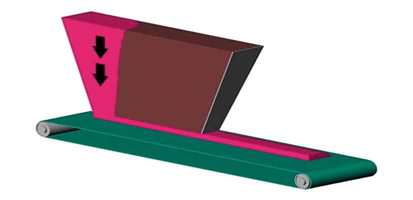
If the gap between the bin interface and belt is constant along the length of the outlet with capacity set by the opening of a front gate, material will be withdrawn preferentially from one end of the outlet. If the outlet through which the bulk solid is expected to flow is too narrow, arching due to interlocking of large particles or cohesive strength of smaller particles can prevent material from discharging. If the interface between the hopper and belt feeder is not properly designed to discharge material uniformly over the entire cross section, a funnel flow pattern (see Figure 1) will develop with the additional potential problem of ratholing. These issues can result in flow at either the back or front end depending on the front gate opening (header image).

With fine powders, the discharge rate may be limited if the belt feeder is operating at a speed greater than the bulk solid’s critical steady state rate of discharge. Similarly, flooding of fine powders is a common problem if the interface is not designed for uniform withdrawal or if the bin is not designed for mass flow. A proven design that eliminates most of the problems just described is shown in Figure 2.
Since the idlers of a belt feeder can be mounted on load cells, can be used in either a volumetric or gravimetric application. Belt feeders have many moving parts and are prone to spilling material from return idlers. They therefore generally require more attention and maintenance than a well-designed screw or vibrating pan feeder. It is important to ensure that the maximum feed rate from the upstream device is always greater than the maximum required operating rate of the feeder. Otherwise, the feeder will become starved, and rate control will be lost. This problem is particularly pronounced when handling fine powders, since their maximum rate of flow through an opening is significantly less than that of coarser bulk solids whenever a mass flow pattern is used.
If the gap between the bin interface and belt is constant along the length of the outlet with the capacity set by the opening size of a front gate, as example, material may be withdrawn preferentially from one end of the outlet. The key to proper belt feeder design is to ensure increasing capacity along the length of the bin outlet by providing expansion in both plan and elevation. It is also important that the clearance between the belt and frond end of the outlet be at least 1.5 to two times the largest particle size to prevent blockage.
Mechanical arching due to interlocking of large particles or cohesive arching due to a material’s cohesive strength can prevent material from discharging through an undersized outlet. Therefore, the minimum outlet width at the rear end of the interface must be greater than or equal to the critical dimension to prevent a stable arch from forming. The sloping side walls must be at least as steep as the hopper wall slope required for mass flow. The slot length should be at least three times the width in order to realise the benefits of a rectangular outlet. Often it is advantageous to use a much longer slot with large silos or with wedge or chisel-shaped hoppers containing vertical end walls.
Both the minimum outlet width and required hopper angle can be calculated from measured flow properties of the material.
One design approach is to start with standard 20° picking idlers with the centre roll being wider than the width of the interface at the front to set the initial belt width. A reasonable gap between the interface and belt is then chosen and use of a shallow angle of surcharge, allows for quick determination of whether a wider belt is required to prevent spillage or if a slower belt speed is appropriate.
There are trade-offs to be considered, such as capital and operating costs between a wide belt operating at low speed and a smaller belt operating at higher speed. Another consideration is the power consumption of different belt sizes. Wider belts require more belt tension but may require less power if speed is reduced. However, low speed belts require high ratio gear reducers, which will result in more drive loss than standard units.
Taper of the slot in elevation must be sufficient for particles to freely form an angle of surcharge on the belt. The gap between the interface and the belt at the front end must be at least three times the normal maximum particle size and must be greater than the maximum possible particle size. Once a front-end gap has been selected for the desired slot length, the belt’s size and speed can be determined. This process can then be repeated with a different belt size, type of belt, type of idler, or slot length to obtain an optimal configuration.
At the tail end, troughing of the belt, if necessary, can be accomplished with transition idlers beneath the hopper interface. This allows the centreline of the tail pulley to be located closely behind the rear of the interface. The belt line work point should be the top of the idlers and pulleys, so as to avoid belt lift when starting the feeder. If required, detroughing of the belt can start a short distance downstream of the interface however, the centreline of the head pulley must be located beyond the material’s angle of surcharge in order to prevent spillage from the belt.
Other important aspects of belt design include:
- A slanted ‘nose’ with an arch-shaped cut-out to provide stress relief and prevent stagnation at the front or discharge end.
- Capacity should be set by belt speed and not by an adjustable front gate.
- A flexible rubber or plastic buffer at the rear end to allow a gap for uniform material withdrawal without belt or interface damage.
- Spillage skirts that expand slightly in the direction of belt travel and that are remote from the feeder interface. This prevents the skirts from interfering with uniform withdrawal.
- Replacing side rolls with slider bars within the hopper/feeder interface region to eliminate uneven skirt wear, spillage due to belt sag, and high loads on idlers.
- Properly designed and well-maintained belt scrapers, which are critical to minimising the amount of spillage due to carry-back.
Drive types
Two main drive types are available: electrical/mechanical and hydraulic. Electrical/mechanical drives are capable of operating over a 10:1 speed range by varying the motor frequency. However, the drive’s output torque, efficiency and temperature will change with frequency, which must be considered in the selection of the drive. Electrical/mechanical drives can deliver up to 300 per cent of their rated torque during start-up, which helps to overcome feeder start-up loads. Hydraulic drives have constant output torque from 0 to 100 to per cent of design speed, providing a larger operating range. Hydraulic drives are compact, shaft-mounted units, and usually smaller than an equivalent electrical/mechanical drive. This is particularly beneficial with slow speed drives since they require large gearboxes to provide the desired output speed.
Power considerations
Sometimes the power required to shear material and operate a belt feeder exceeds the available drive power. This problem is usually the result of an improperly designed interface that does not allow uniform withdrawal over the entire cross section of the outlet. If the feeder interface is not structurally designed to withstand the pressures exerted by the bulk solid, it will deform in such a way that significantly higher forces are needed to shear the material [1].
Knowledge of the material loads acting on the portion of a belt feeder below a hopper outlet is an essential component in determining drive details. The first factor is the vertical material load acting on the belt, which is used for determining belt support requirements and the required tension in the belt to overcome drag of the supports. The second factor is the force (belt tension) required to shear the material from beneath the interface. Both of these loads are sensitive to interface geometry and loading conditions; consequently, the approach developed by CEMA [2] for belt conveyors does not apply to belt feeders.
Using an approach based on the work of Jenike [3] and assuming that the bin and belt feeder interface provide mass flow, the vertical load can be expressed as:
A x F + B
Where:
A = integrated vertical material force at the shear plane (generally assumed to be at the bottom of the interface)
F = dimensionless multiplier used to correct for different loading conditions
B = weight of material between shear plane and belt
The shear load can be expressed as:
C x F
Where:
C = Value of A multiplied by the effective coefficient of internal friction, usually taken as (sin δ).
The value of dimensionless multiplier F is close to 1 during steady state running conditions but can easily exceed a value of 3 during start-up, particularly if there is significant relative deflection between the hopper interface and feeder. Other factors that influence F include outward deflection of the interface walls [1], belt sag between idlers, and filling of the bin from empty.
It is common to find that the value of F dominates the material loads acting on a belt feeder; consequently, design details and experience are critical. One approach to minimising material loads is to maintain a sufficient heel (i.e., minimum material level) above the belt. This will help to isolate the belt from overpressures developed during refilling of the bin and prevent excessive belt wear due to impact of hard particles. Another approach, which can be used in conjunction with a material heel, consists of mounting the belt interface rigidly to the feeder frame and using a connection that allows vertical slip between the hopper and interface in order to isolate the belt from any relative deflection. The location of this connection must be approximately one outlet width or more above the bottom of the interface in order to be fully effective. A similar effect can be achieved by operating the belt whenever material is added to the bin or by mounting the belt on flexible supports.
Conditions at and below the hopper outlet are just as important as the overall container geometry. Understanding the flow properties for your bulk material and how equipment design affects flow patterns and possible development of flow obstructions in storage containers and feeders will ensure that you are protected against baked in design flaws. By following well-proven design rules, belt feeders can perform reliably and with minimum power, but a mass flow interface is critical.
Do you have a bulk solids handling question? Jenike & Johanson has developed the science of bulk solids flow and specialises in applying it to solving the most challenging bulk solids handling problems. So why not put them to the test with your question? The harder, the better.
Note: The advice here is of a general nature. Specific solutions are very sensitive to their circumstances; therefore, you should consult with a specialist in the area before proceeding.